


Load carrier*
Introduction
The specifications, constructional data and illustrations contained in this publication are not binding. We reserve the right to make modifications without prior notice.
Follow the instructions carefully when installing the load carriers.
Note
Key number
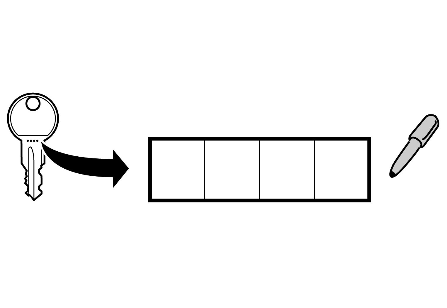
Please note down the number of your key in the box above. If the key is lost then it can be reordered.
Installing the load carriers
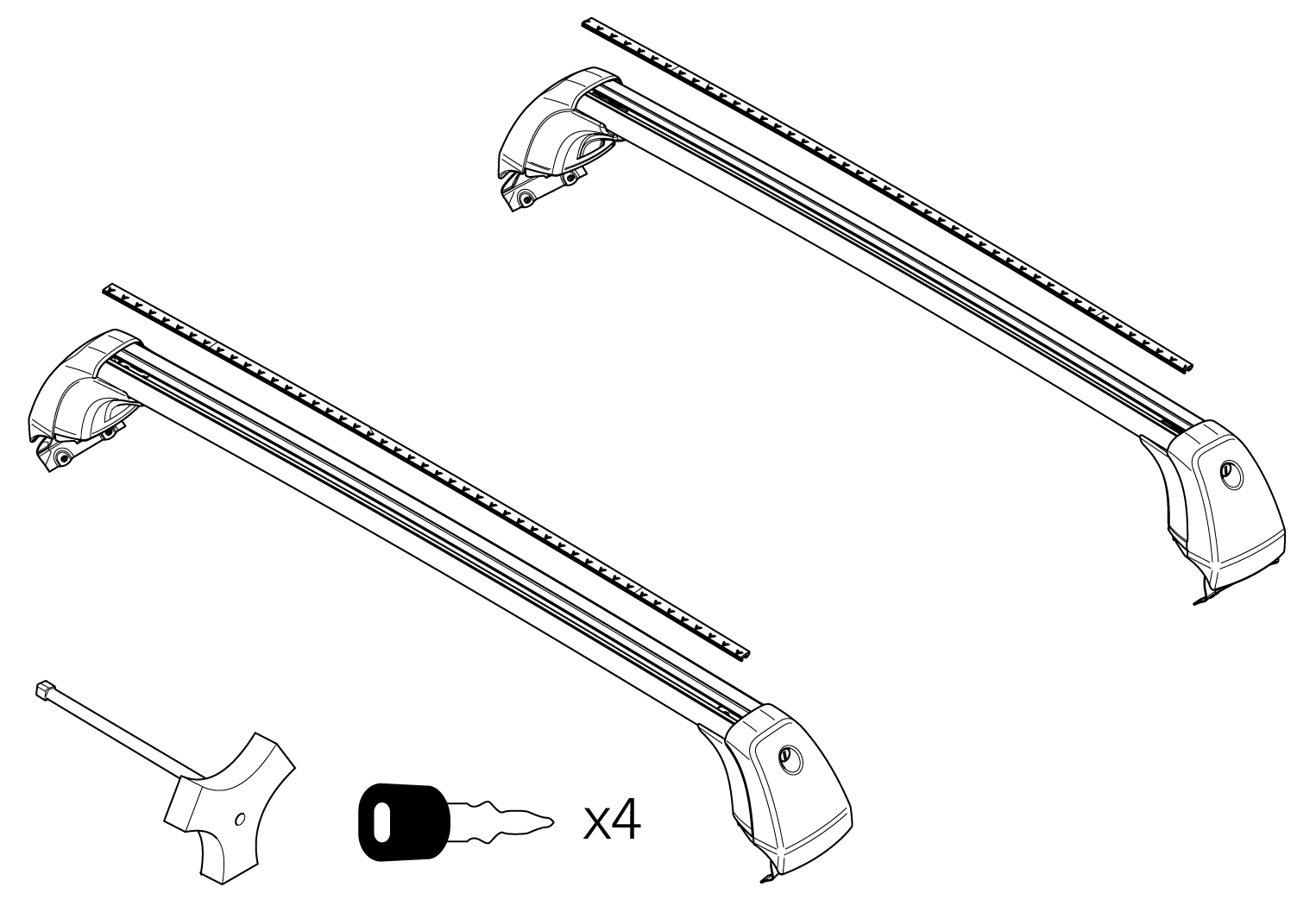
Kit contents
Preparations
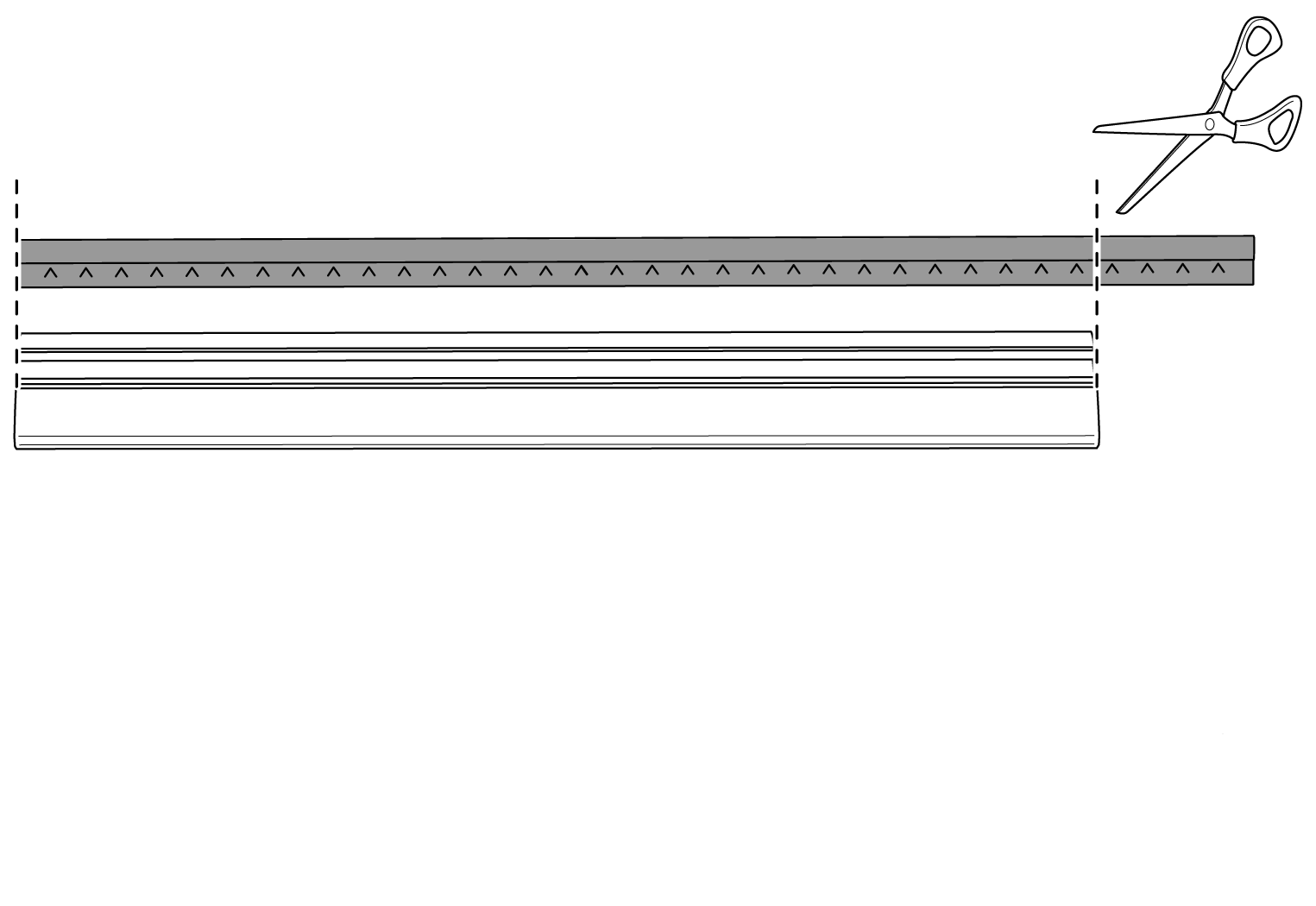
When installing for the first time, the trim needs to be cut to the correct length.
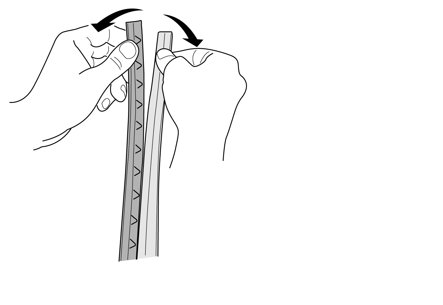
Then pull apart the T-track trim.
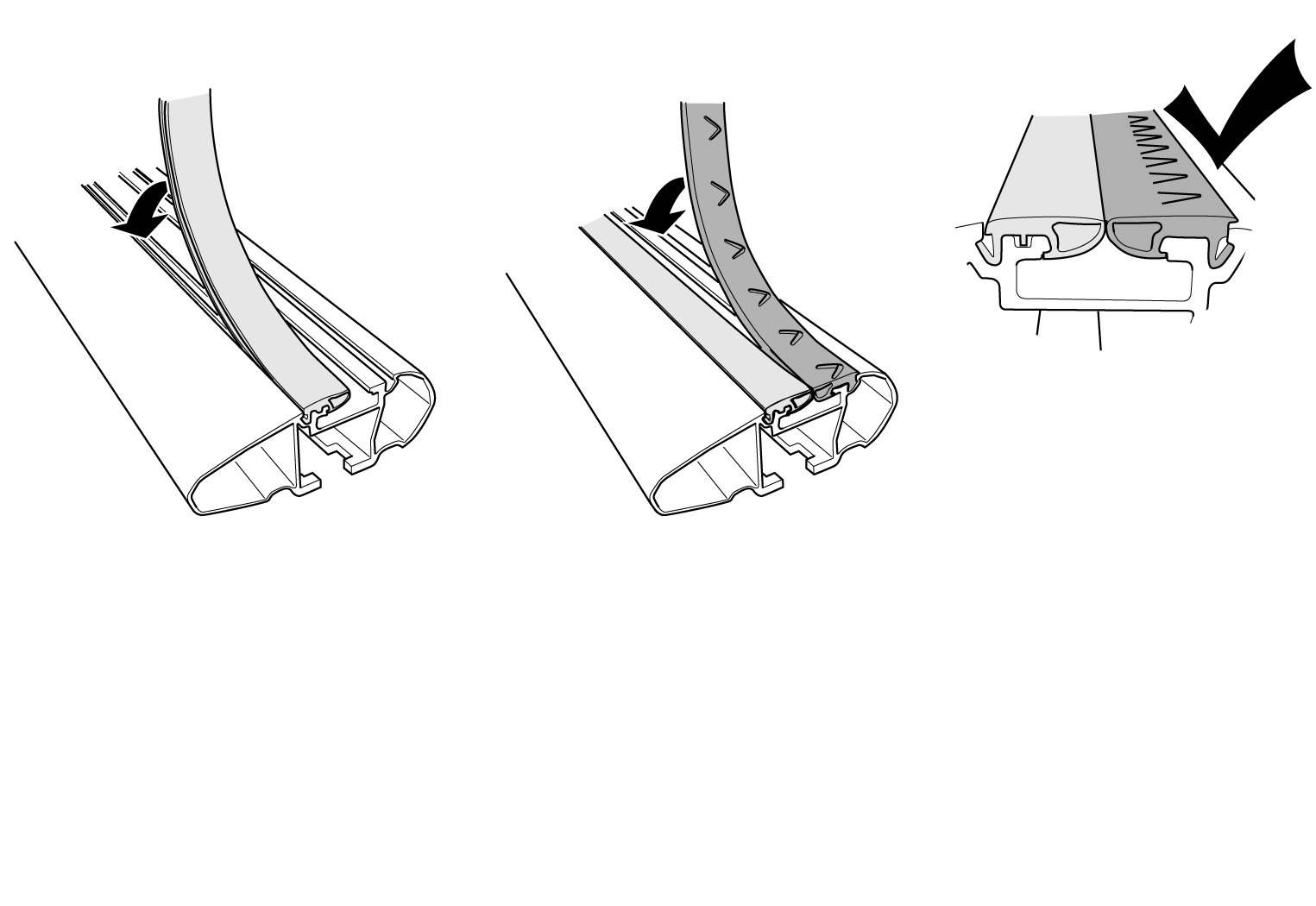
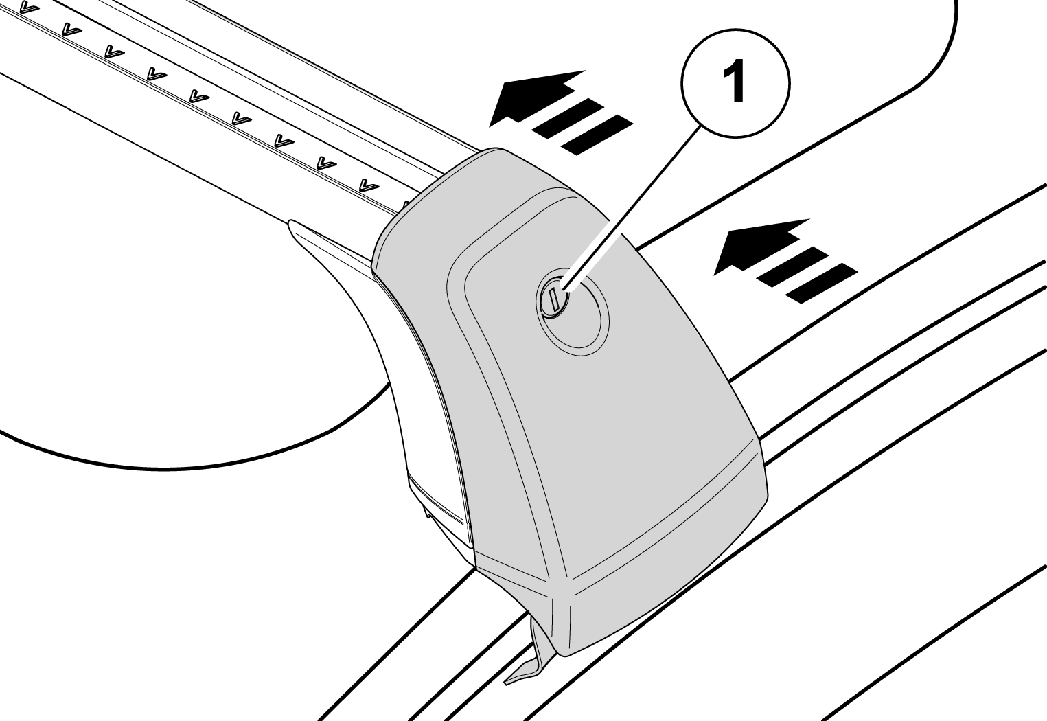
Apply the trim to the load carrier. The arrows on the trim show the installation direction. The arrows should point towards the front of the car.
Positioning the load carriers
Note
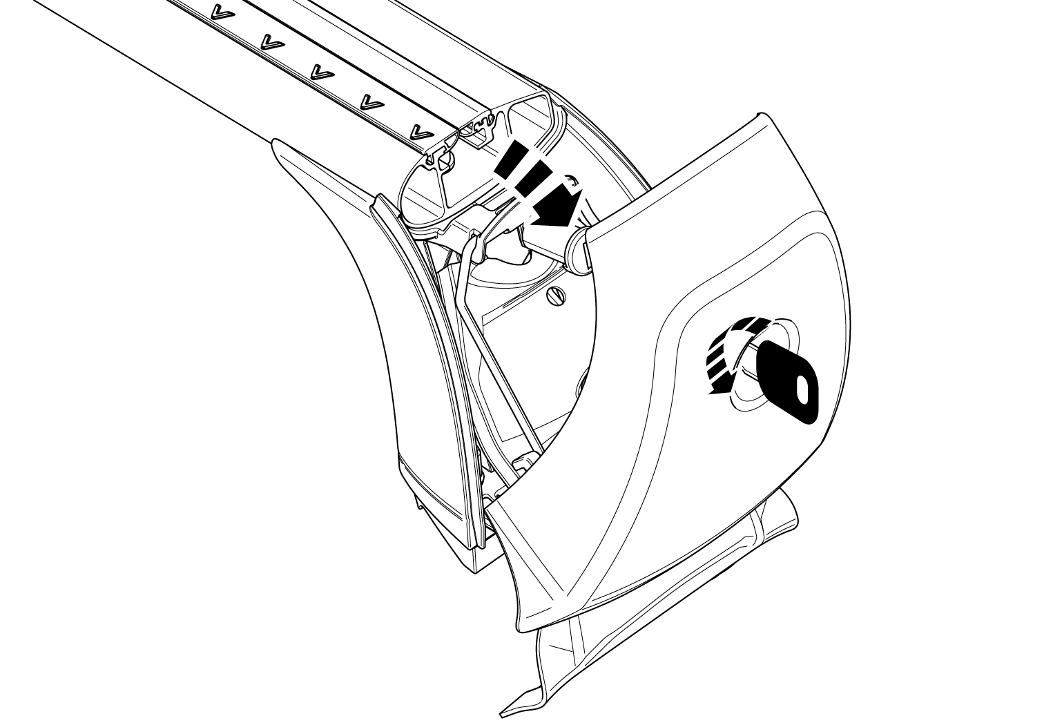
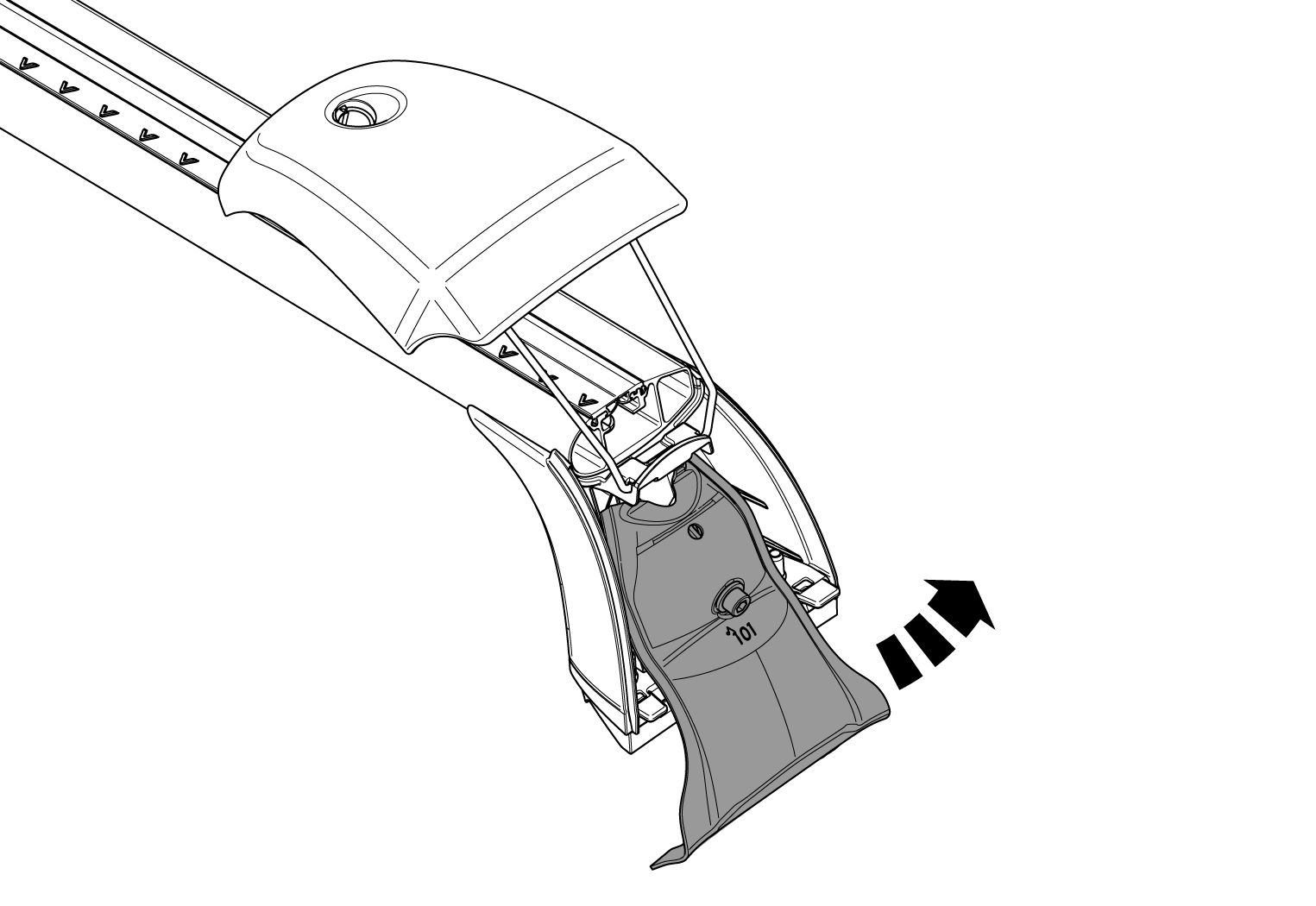
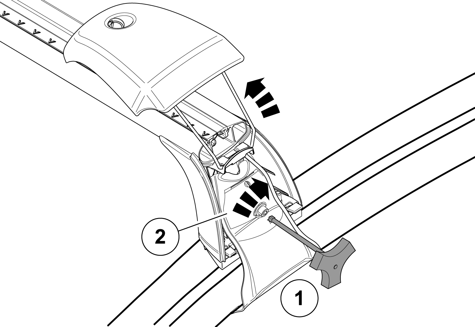
Loosen the covers on the load carriers by turning the locking key 90° anticlockwise, and then carefully loosen the cover.

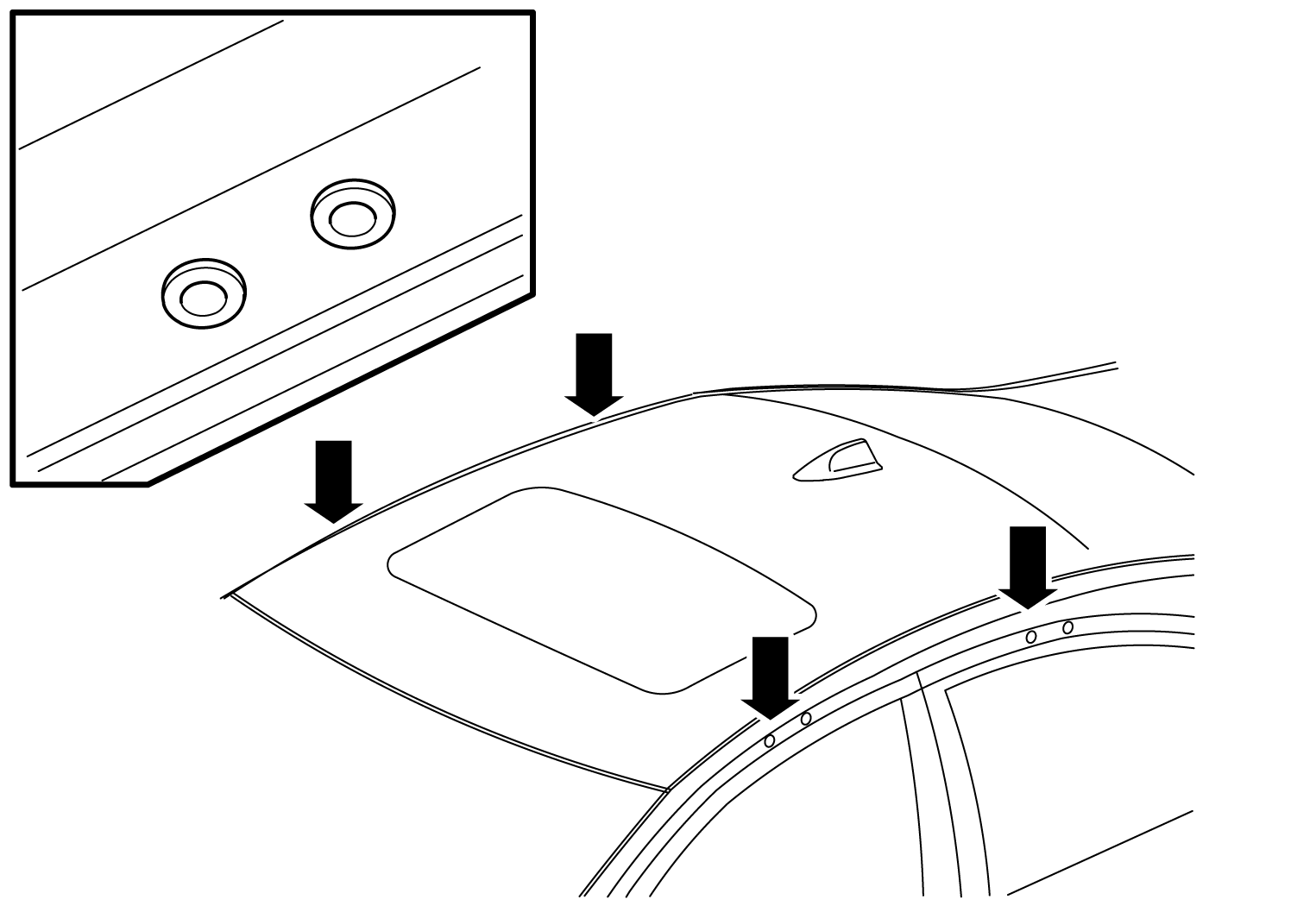
To install the right load carrier in the right place, see the decal located under the load carrier.
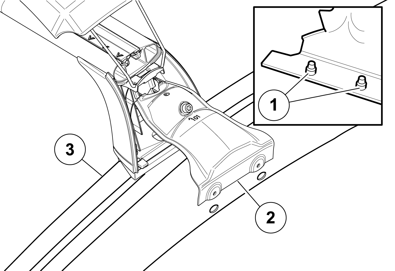
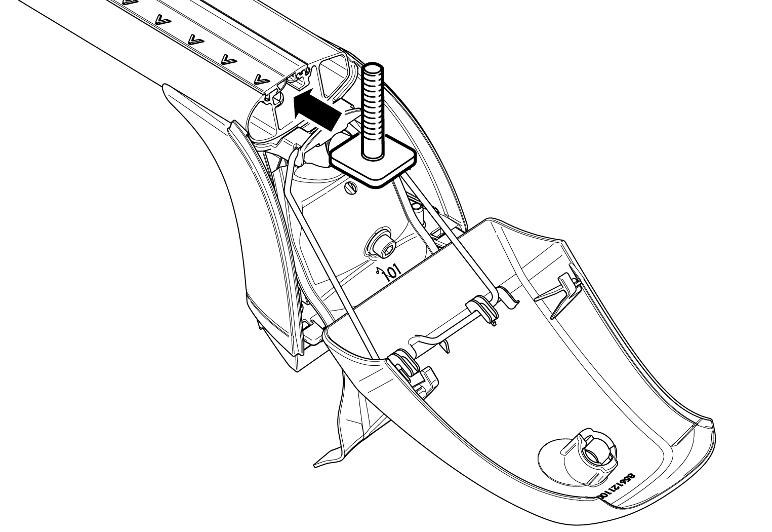
Position one of the load carrier's feet at the edge of the roof, so that the pins  on the attaching brace are in line with the rivet nuts
  in the door frame.
 on the load carrier's foot is in contact around the equivalent curvature on the top side of the roof edge.
Note
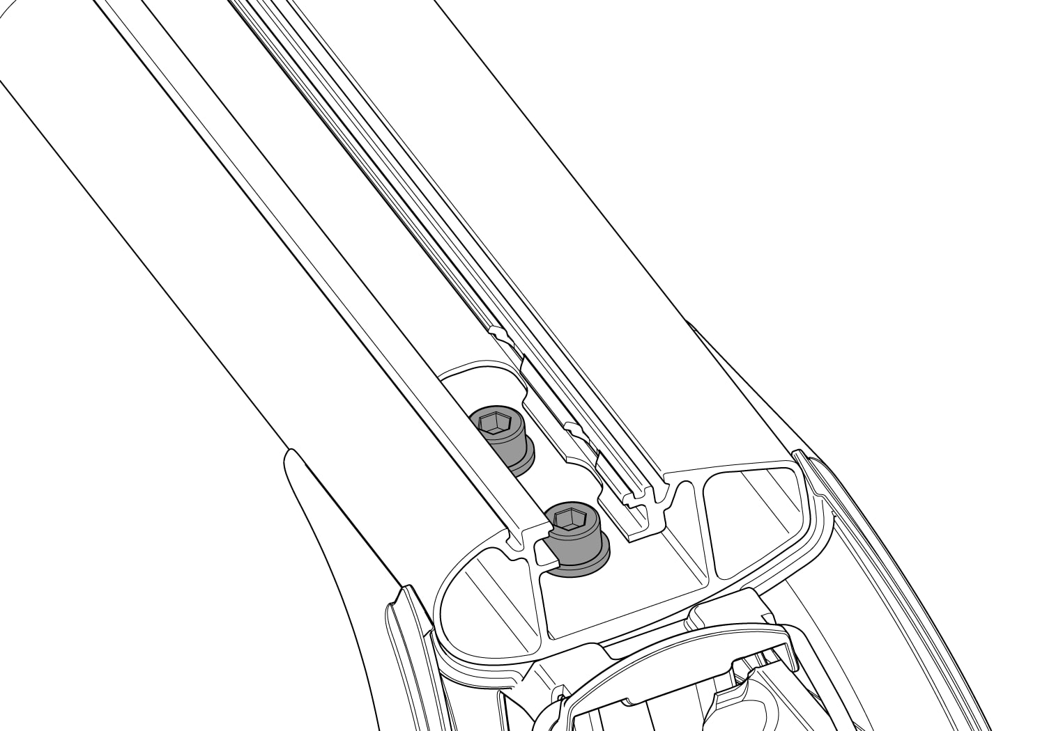
Position the attaching brace down against the roof edge.
Note
become free from the edge of the roof. Loosen the screw if necessary. so that the pins do not fall out of the rivet nuts.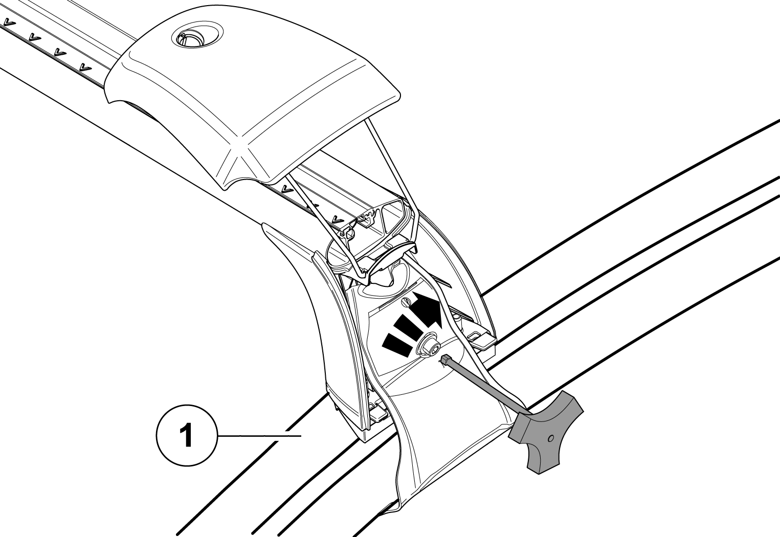
Check that the load carrier's foot is in contact with the edge of the roof.
Reinstall the covers on the end faces of the load carriers and turn the locking key 90° clockwise.
When using T-groove kit
Safety instructions
Note
- Maximum permitted roof load and total weight for the car must not be exceeded (see the owner's manual for the car). Maximum roof load consists of the total of the load carriers' unladen weight, accessories and load.
- Distribute the load evenly over the loading surface, with as low a centre of gravity as possible, and secure it so that it cannot come loose.
- Check the position and securement of the load at regular intervals
- Check bolted joints and brackets after a short driving distance. If necessary, tighten to the prescribed torque. Check at regular intervals.
- The car's driving characteristics and crosswind sensitivity are changed by a load on the roof. Adapt speed according to vehicle load (max. 130 km/h / 80 mph). Always follow applicable speed limits and other traffic laws.
- For the safety of other road users and to save energy, remove the load carriers when not in use.